| PART NUMBER |
DESCRIPTION |
BOX
QTY |
A7-8 |
Fits Hilti® P2000 dispensing tools
8 Fluid Ounce Cartridge A7 |
12 |
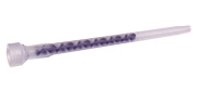
A24 |
Mixing Nozzle for A7-8 Cartridge
Nozzle diameter fits 3/8" to 5/8" holes
(overall length of nozzle 6-3/8") |
24 |
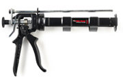
A101 |
Heavy Duty Hand Dispenser for A7-8 Cartridge |
1 |
|
A7
8 Fluid Ounce Cartridge
|
Number of Anchoring Installations per Cartridge* Using Reinforcing Bar with A7 Adhesive in Solid Concrete |
| REBAR |
DRILL
HOLE
DIA.
INCHES |
EMBEDMENT DEPTH IN INCHES (mm) |
1
(25.4) |
2
(50.8) |
3
(76.2) |
4
(101.6) |
5
(127.0) |
6
(152.4) |
7
(177.8) |
8
(203.2) |
9
(228.6) |
10
(254.0) |
11
(279.4) |
12
(304.8) |
13
(330.2) |
14
(355.6) |
15
(381.0) |
| #3 |
7/16 |
187.8 |
93.9 |
62.6 |
46.9 |
37.6 |
31.3 |
26.8 |
23.5 |
20.9 |
18.8 |
17.1 |
15.6 |
14.4 |
13.4 |
12.5 |
| #4 |
5/8 |
105.7 |
52.9 |
35.2 |
26.4 |
21.1 |
17.6 |
15.1 |
13.2 |
11.7 |
10.6 |
9.6 |
8.8 |
8.1 |
7.6 |
7.0 |
| #5 |
3/4 |
81.1 |
40.5 |
27.0 |
20.3 |
16.2 |
13.5 |
11.6 |
10.1 |
9.0 |
8.1 |
7.4 |
6.8 |
6.2 |
5.8 |
5.4 |
| #6 |
7/8 |
65.5 |
32.7 |
21.8 |
16.4 |
13.1 |
10.9 |
9.4 |
8.2 |
7.3 |
6.5 |
6.0 |
5.5 |
5.0 |
4.7 |
4.4 |
| #7 |
1 |
60.5 |
30.2 |
20.2 |
15.1 |
12.1 |
10.1 |
8.6 |
7.6 |
6.7 |
6.0 |
5.5 |
5.0 |
4.7 |
4.3 |
4.0 |
| #8 |
1-1/8 |
50.2 |
25.1 |
16.7 |
12.6 |
10.0 |
8.4 |
7.2 |
6.3 |
5.6 |
5.0 |
4.6 |
4.2 |
3.9 |
3.6 |
3.3 |
| # 9 |
1-1/4 |
29.1 |
14.6 |
9.7 |
7.3 |
5.8 |
4.9 |
4.2 |
3.6 |
3.2 |
2.9 |
2.6 |
2.4 |
2.2 |
2.1 |
1.9 |
| #10 |
1-1/2 |
23.8 |
11.9 |
7.9 |
6.0 |
4.8 |
4.0 |
3.4 |
3.0 |
2.6 |
2.4 |
2.2 |
2.0 |
1.8 |
1.7 |
1.6 |
| #11 |
1-3/4 |
14.6 |
7.3 |
4.9 |
3.6 |
2.9 |
2.4 |
2.1 |
1.8 |
1.6 |
1.5 |
1.3 |
1.2 |
1.1 |
1.0 |
1.0 |
* The number of anchoring installations is based upon calculations of hole volumes using ANSI tolerance carbide tipped drill bits,
the nominal areas of the reinforcing bars and the stress areas of the threaded rods. These estimates do not account for waste.
|
A7
8 Fluid Ounce Cartridge
|
Number of Anchoring Installations per Cartridge* Using Threaded Rod with A7 Adhesive in Solid Concrete |
ROD
In. (mm) |
DRILL
HOLE
DIA.
INCHES |
EMBEDMENT DEPTH IN INCHES (mm) |
1
(25.4) |
2
(50.8) |
3
(76.2) |
4
(101.6) |
5
(127.0) |
6
(152.4) |
7
(177.8) |
8
(203.2) |
9
(228.6) |
10
(254.0) |
11
(279.4) |
12
(304.8) |
13
(330.2) |
14
(355.6) |
15
(381.0) |
| 1/4 (6.4) |
5/16 |
259.5 |
129.7 |
86.5 |
64.9 |
51.9 |
43.2 |
37.1 |
32.4 |
28.8 |
25.9 |
23.6 |
21.6 |
20.0 |
18.5 |
17.3 |
| 3/8 (9.5) |
7/16 |
150.2 |
75.1 |
50.1 |
37.6 |
30.0 |
25.0 |
21.5 |
18.8 |
16.7 |
15.0 |
13.7 |
12.5 |
11.6 |
10.7 |
10.0 |
| 1/2 (12.7) |
9/16 |
108.1 |
54.1 |
36.0 |
27.0 |
21.6 |
18.0 |
15.4 |
13.5 |
12.0 |
10.8 |
9.8 |
9.0 |
8.3 |
7.7 |
7.2 |
| 5/8 (15.9) |
11/16
3/4 |
77.6
55.4 |
38.8
27.7 |
25.9
18.4 |
19.4
13.8 |
15.5
11.1 |
12.9
9.2 |
11.1
7.9 |
9.7
6.9 |
8.6
6.1 |
7.8
5.5 |
7.1
5.0 |
6.5
4.6 |
6.0
4.3 |
5.5
4.0 |
5.2
3.7 |
| 3/4 (19.1) |
13/16
7/8 |
54.7
43.6 |
27.3
21.8 |
18.2
14.6 |
13.7
10.9 |
10.9
8.8 |
9.1
7.3 |
7.8
6.3 |
6.8
5.5 |
6.1
4.9 |
5.5
4.4 |
5.0
4.0 |
4.6
3.6 |
4.2
3.4 |
3.9
3.1 |
3.6
2.9 |
| 7/ 8(22.2) |
15/16
1 |
52.5
36.4 |
26.2
18.2 |
17.5
12.2 |
13.1
9.1 |
10.5
7.3 |
8.7
6.1 |
7.5
5.2 |
6.6
4.5 |
5.8
4.0 |
5.2
3.6 |
4.8
3.3 |
4.4
3.0 |
4.0
2.8 |
3.7
2.6 |
3.5
2.4 |
| 1 (25.4) |
1-1/16
1-1/8 |
44.9
34.4 |
22.4
17.2 |
15.0
12.0 |
11.2
8.6 |
9.0
7.5 |
7.5
6.0 |
6.4
5.0 |
5.6
4.3 |
5.0
3.7 |
4.5
3.3 |
4.1
3.0 |
3.7
2.7 |
3.5
2.5 |
3.2
2.3 |
3.0
2.1 |
| 1-1/4 (31.8) |
1-5/16
1-3/8 |
28.7
22.4 |
14.4
11.2 |
9.6
7.6 |
7.2
5.6 |
5.7
4.5 |
4.8
3.8 |
4.1
3.2 |
3.6
2.8 |
3.2
2.5 |
2.9
2.3 |
2.6
2.1 |
2.4
1.9 |
2.2
1.7 |
2.1
1.6 |
1.9
1.5 |
* The number of anchoring installations is based upon calculations of hole volumes using ANSI tolerance carbide tipped drill bits, the nominal areas of the reinforcing bars and the stress areas of the threaded rods. These estimates do not account for waste.